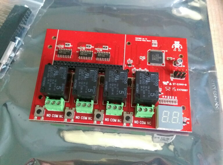
When they aren’t selling add-on boards or taking sacks to the post office the people over at ModMyPi are inventing new Raspberry Pi products. Their latest home-grown product is a quad relay board. They sent me one to try out and although I received it for free it came with no conditions or restrictions. The following opinions are my own impartial thoughts.
A relay is an electrically operated switch which allows you to switch a load by passing a current through a coil. The advantage with a relay is that you can switch a large voltage load with a smaller voltage from a completely separate circuit. For more information about relays in general you can read the ModMyPi introduction to relays or the Wikipedia Relay entry.
The principle is fairly easy but using relays in practice can require a little more consideration and effort. Some of this can be avoided by using a standard relay board but these still leave you with some headaches. Why? Well a cheap relay board will usually :
- Not give you much idea about the actual relay fitted
- require some jumper settings
- not give you much help in setting the jumpers or connecting
- risk relays switching on and off while your Pi boots and you get control of the GPIO pins in your software
The PiOT aims to address these issues and works with the Raspberry Pi B+/2/3 and Zero which all share the same 40 pin GPIO arrangement.
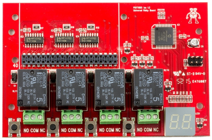
Specification & Features
- 4 x OMRON G5LA-1 Relays for Switching up to 10A @ 250VAC, or 10A @ 24VDC
- 4 x Tactile Buttons for GPIO/Relay Bonding
- Two-Digit 7 Segment Display for Visual Feedback & Setting Control
- Micro-controlled GPIO/Relay Setting & Switching (No Jumpers Required!)
- 40 Point Raspberry Pi GPIO Modeled Input
- 5V & 3.3V Input Compatible
- Low Holding Current via PWM ~ 100mA per Relay Board
- Stackable Relay Board (Up to 5 Without External Power)
- Multiple Start-Up Modes to Negate Boot GPIO Chatter (Delayed/Handshake)
- Pi Zero Mounting Points
- Overall size 72mm x 110mm
Some of that may make it sound more complicated than it is but some of those features mean you can spend more time on your software and less time fiddling with wires.
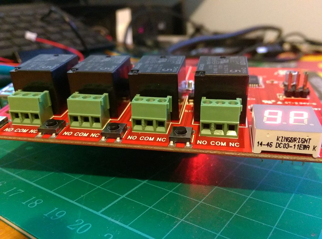
The most obvious feature that marks this board out from the others is that it has some on-board intelligence. Using the buttons and seven segment display it can be configured to use GPIO signals of your choosing and it keeps the relays stable until you are ready to control them in software. This gives you a more predictable system and if you are switching mains electricity this is a really important design feature.
The startup modes make it a lot easier to predict the state of your relays when the system starts up. For most relay based applications I can think of this is good news.
Switching Mains Electricity
If you are switching mains loads you need to exercise caution! Not just when you build your invention but during testing and use. Accidents happen when you drop your guard. Take no risks with electrical safety. You also need to ensure your device is suitably mounted and protected from children, pets and other adults! Blowing up LEDs and burning yourself with soldering irons is all part of the fun. Getting electrocuted, electrocuting someone else or starting a fire isn’t. Stay safe out there people!
Getting Started
 To get started I mounted the board on a Pi 2 Model B using the supplied metal pillars. It’s important to make sure the board is firmly attached to the Pi to avoid inconsistent GPIO contacts.
Then I pressed the buttons next to the relays to set the GPIO numbers I wanted to assign to each relay. There is more detail on this process on the Basics page of the PiOT Wiki. I set the relays to use GPIO 5,6,13 and 19.
Next up was the startup mode. There are a few modes available (as detailed in the Wiki) but I wanted to start with “handshake” mode. This means the relays are all off until the board receives a specific sequence on GPIO2. So in a Python script you can send the sequence when you are ready to use the relays.
This configuration is really easy once you know what to do! Here is a video I created showing the basics :
The official Wiki is on Github and provides an example Python script with a GUI. It’s easy to install and lets you toggle GPIO outputs so you can test your relays. When you click the appropriate GPIO you can hear the relay click. The connect/disconnect button sends the handshake sequence to enable the board if you are using that mode.
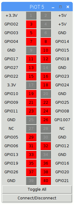
I wanted something a little more basic without the GUI so I created my own test script …
Python Test Script
My script does the following :
- Defines the GPIO numbers associated with my board
- Defines a function to send the handshake signal
- Configures the 5 GPIO pins we need using standard RPi.GPIO commands
- Four GPIO pins for the relays are set to a LOW state so we are starting from a known state
- Sends the handshake sequence to enable the board
- Toggles the state of the relays in a loop
- Sends the handshake sequence to disable the board
You can download my test script directly to your Pi using :
wget https://bitbucket.org/MattHawkinsUK/rpispy-misc/raw/master/python/piot_relay.py
and then run it using :
sudo python piot_relay.py
The script sends the handshake sequence to GPIO2 which enables the board. It then toggles the four relays in sequence for a number of iterations. You will see the indicators on the 7-segments displays change as well as hear the relays click.
You can make changes using the nano text editor :
nano piot_relay.py
This basic mechanism can be used in your own projects to control the relays as required.
Overall Impressions
I really like this board. The jumper free configuration is a pleasure to use. Just make sure if you use the buttons on the board you are aware of any wires you have connected to the terminal blocks. If you are switching high voltages it’s probably best to turn off those circuits completely while you re-configure the relay board.
The design of the main connector means you can use this add-on with any 40-pin header variant of the Pi. The full size Pi’s don’t sit in the same footprint but for most automation projects I would suggest you mount everything in an enclosure so this is less of a problem. I’ve found for these sort of applications the robustness of the connections and wiring is more important than overall size.
Buy
The board is available from the PiOT Relay Board page at ModMyPi. It is priced at £23.99. A case is also available which is big enough to include a Raspberry Pi and the PiOT Relay Board.
You can also try searching Amazon for “PiOT relay board”.

