Last month I bought myself a 3D printer. It uses standard micro-switches to register the position of the movable parts. I wanted to replace these with something less mechanical and someone on the support forum mentioned using a hall effect sensor instead.
A hall effect sensor can detect the presence of a magnetic field and is often used for positioning objects or measuring rotation. For example you could use one to measure the speed of a bike wheel by attaching a magnet to one of the spokes.
In order to test the idea and check the distance at which the sensor would trigger I decided to use a Raspberry Pi and a bit of Python.
 Hall Effect Sensor
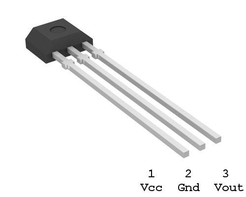
The sensor I chose was an Allegro hall effect sensor A1120EUA-T. It cost approximately £1 from CPC. For any old-timers out there, no it isn’t one of these.
Here is the pin assignment :

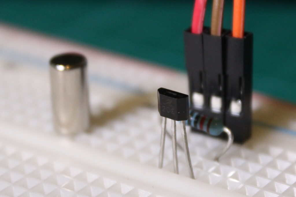
Magnet
 I wanted a cheap, compact magnet that I would be able to easily mount on the printer so I ordered some from Amazon. There was no real science to this and involved a little bit of guess work. I went for some “N48 Grade Rare Earth Neodymium” magnets that were small cylinders measuring 5 x 10mm. They cost £4 for 50 magnets.
Circuit

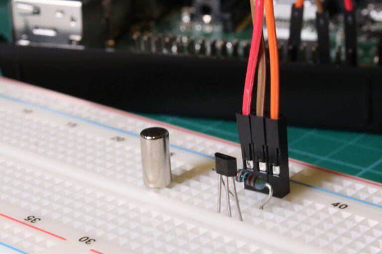
In the photo above the red wire is Vcc (3.3V), the brown wire is ground and the orange wire is Vout.
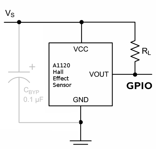
Here is the circuit diagram :

Vcc is connected to the 3.3V supply on the Pi’s header (pin 1). GND is connected to pin 6. Vout is connected to pin 11 (GPIO17) although you can use any of the spare GPIO pins. A 10K (or similar) resistor pulls the output high. The manufacturer recommends putting a 0.1uF capacitor between Vcc and GND to reduce noise but I found it worked fine without it.
| Pi Header | A1120 |
|---|---|
| 3.3V (Pin 1) | Pin 1 |
| Gnd (Pin 6) | Pin 2 |
| GPIO17 (Pin 11) | Pin 3 |
Rather than use an external pull-up resistor I used the internal resistors available on the Pi’s GPIO pins.
Example Python Code
The Python script I wrote simply configured the GPIO pin as an input, pulled it high and setup a call-back function. Whenever the state of the sensor changed it fired the call-back function and printed some text. GPIO17 went “low” when a magnet was near the sensor and returned to “high” when the magnet was removed.
It’s not very complicated and can be downloaded directly to your Pi using :
wget https://bitbucket.org/MattHawkinsUK/rpispy-misc/raw/master/python/hall.py
The script can be run in Python 2 using :
python hall.py
or if you are in Python 3 using :
python3 hall.py
Triggering Distance
I quickly found out that the triggering distance was approx 15mm. This made the setup perfect for my application. This assumed that the end of the cylinder is inline with the flat face of the hall effect sensor. Other magnets would almost certainly result in a different triggering distance so you may have to experiment with alternative magnets if your application requires a different distance.


4 Comments
Hi Matt,
I too have also been looking for an alternative to the microswitch for the Z-end-stop on my 3D printer. In your experiments, did you notice any hysteresis in the hall effect sensor. Ie, you said the sensor triggered at approx 15mm. However, at what distance did the sensor then return to normal when you withdrew the magnet?
Great article!
Hi Gavin, I’ve just given it a quick test and I had to withdraw the magnet about 3-4mm. I’m hoping this will be OK for my printer to complete it’s calibration cycle.
does the Raspberry read the analogue signal …I think you need and ADC ?
This sensor is digital so either presents a logic High or Low to the Pi’s GPIO pin. So no need for an ADC.