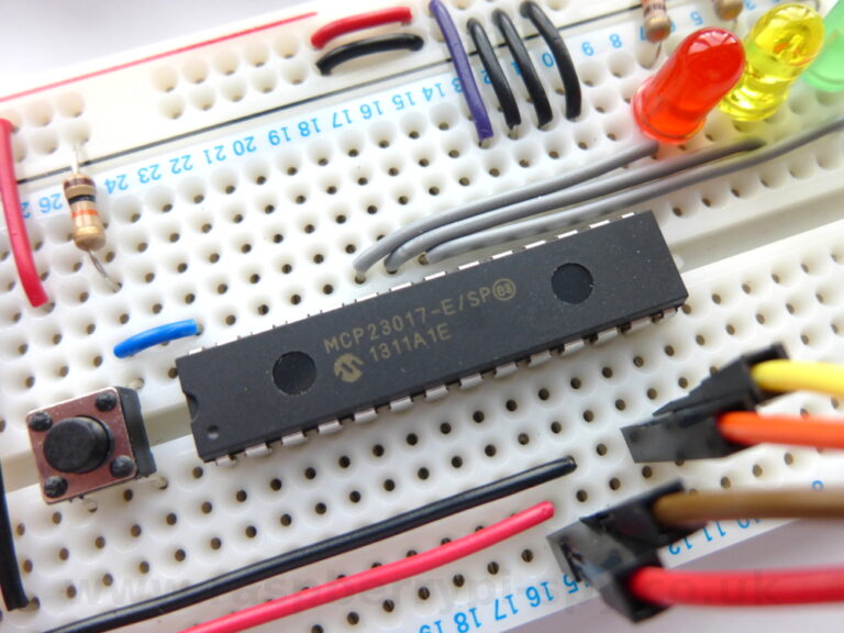
 In How To Use A MCP23017 I2C Port Expander With The Raspberry Pi – Part 2 I explained how to use an MCP23017 16-bit port expander to provide additional outputs. In this article I’ll show a basic input example where we read the status of a push switch.
In our example circuit the switch input uses the last bit of the GPA set of pins.
Python Script For Inputs
Here is an example script which will read the status of the switch in a loop and print message when it is pressed :
import smbus
import time

#bus = smbus.SMBus(0)  # Rev 1 Pi uses 0
bus = smbus.SMBus(1) # Rev 2 Pi uses 1

DEVICE = 0x20 # Device address (A0-A2)
IODIRA = 0x00 # Pin direction register
GPIOA  = 0x12 # Register for inputs

# Set first 7 GPA pins as outputs and
# last one as input.
bus.write_byte_data(DEVICE,IODIRA,0x80)

# Loop until user presses CTRL-C
while True:

  # Read state of GPIOA register
  MySwitch = bus.read_byte_data(DEVICE,GPIOA)

  if MySwitch & 0b10000000 == 0b10000000:
   print "Switch was pressed!"
   time.sleep(1)
You can download direct to your Pi using :
wget https://bitbucket.org/MattHawkinsUK/rpispy-misc/raw/master/mcp23017/mcp23017_inputs.py
You can run the script using the following command :
sudo python mcp23017_inputs.py
The script above performs the following actions :
- Imports the smbus and time libraries
- Creates an smbus object named “bus”
- Configures some register address constants
- Sets first 7 GPA pins as outputs
- Sets last GPA pin as an input
- Reads the state of the 8th bit and prints a message if it goes high
When you press the button you should see “Switch was pressed!” printed to the screen.
In this example we only used one switch. Using both 8 bit registers (GPA and GPB) you’ve got a total of 16 pins to configure as inputs or outputs. That’s a possible 16 LEDs or switches in whatever combination you like. You just need to configure the IODIRA and IODIRB registers with the correct bit pattern.
Don’t forget to check out the online binary, hexadecimal, decimal number convertor to quickly generate binary, decimal and hexadecimal numbers for your own I2C scripts.


31 Comments
hello, I’ve seen several posts that says one of the restrictions of i2c is the cable length has to be less than 6″. Is that the cable length just between the Pi and the MCP23017? Or does that mean any peripherals attached to the MCP23017 can only be up to 6″ away?
Thanks.
I’m not sure but I did some quick Googling and plenty of people seem to have some sucess with cable lengths measured in metres. If there is a restriction it will be the two I2C lines between the MCP23017 and the Pi. The inputs and outputs on the chip are just normal logic pins.
Old thread, but still…
The length of the cables you’re talking about, are at the output side of the MCP23017 and have nothing to do with I2c. So, there’s not really a length restriction at that side.
I2c, however, is limited because of the line capacitance that should not be larger than 400pF.
There are solutions for that. One of them is using the P82B96 (http://www.ti.com/product/p82b96). When you’re using this device, you can have lengths up to at least 20m (because at the transmission side, you can go up to 4000pF bus capacitance…)
An old question but it maybe helps:
We have extended the bus line and it depends on for example the cable type used. On the next page we have an example of how to extend the bus line. Allthough the shown setup is correct you should use octocouplers to protect the expanded bus part against shorts and interferance.
The chip mentioned below (P82B96 ) is also the one we used and if done correctly you can go up to 50 meters and counting. We also have the spec sheet on this page so you have a table explaining how far you can get at 100khz (which the pi uses by default).
The page is: http://pidome.wordpress.com/manual-howtos/pidome-hardware/i%C2%B2c-bus-extender-for-the-raspberry-pi/
Hello. Any tutorials for how to read a temperature sensor like the DS18B20 using raspberry pi and the MCP23017? Thanks!
I’ve not used one with the MCP23017 but you can easily connect a DS18B20 using GPIO4. See this post.
all my gpio ports are full 🙂
that’s why i use the mcp for port expansion. I’ll try to figure it out myself. Thanks!
Hi ,
Did you get MCP23017 working with DS18B20 ? Or any other sensor with this MCP ? If so can you explain ?
Im looking to really increase the number of GPIO output.. I’m looking for 32 outputs, can I use 2 of these port expanders in parallel?
You can connect two using the same I2C pins on the Pi. You just need to set a different address for the second device using the A0,A1,A2 pins. ie rather than set them all low set A0 high.
Hi there. Great tutorial! Im fairly new at using i2c on the raspberry and have very little experience.. I wanted to know if you can maybe post a diagram of how 2 mcp chips can be connected to the RPi
It’s on my list of things to do! The only real difference is the A0, A1 and A2 pins. One of these must be set high to give the second device a unique address.
Hi there, I’m pretty new to I2C so I was wondering if it is possible to use interrupts with inputs on the MCP? If so could you explain how? If not I will have to stick with the 7 accessible pins on the GPIO header of my Rev 2 RPi.
Hi Samadi (and anyone else that can help),
I’m trying to use the interrupts on the slice of Pi/o mcp23017 with Python and smbus. How did you get on with enabling the interrupt?
I know I need to tie the INT pad back to one of the GPIO pins on the rpi, but I need to know how to tell the mcp23017 to change the INT state during an input change using bus.write_byte_data()
Any examples would be very helpful…
Thanks all,
R
I was searching about this, and came here. Anyone has some idea to do that, and got it working?
Matt, something for part 4?
Thank you in advance.
I have been through part 1 to part 3 and all work really well, thank you. However now I would also like to see if I can use the intrupts with your smbus library and any additional wiring. Did you ever create a part 4 or do you have some sample code or examples. I think I might also need some notes on connecting the INT pin as it look as though you need to connect it to one of the GPIO pins. I would be creatful for any information. Thank you.
The smbus library isn’t mine it’s just one of the libraries out there that everyone uses. I’m not sure who the author is. Unfortunately I haven’t had a chance to ever try out interrupts on the MCP23017.
In my consulting work I find that I have need for a programmable module and with some research find the raspberry pi to be of great interest. I have no use for video, audio or external connection such as TV or monitor. The module would be used to control a plurality of stepper motors and DC motors. Input information would be in multiple tables, or more desirable, with input values of A, B and C and a 6-step formula which would preclude the units to be confined to only the preloaded tables and their attendant high usage of memory. The latter would make the units more universal.
What linux language would be most appropriate? Would like any and all comments.
Thank for your work. It help me to start with i2c study.
Good work.
Thank from Italy
steve
I’d like to use the I2C ports to control 24v solenoid switches (irrigation valves) via an 8-channel opto relay board (such as listed at http://www.ebay.com/bhp/8-channel-relay-board). Would those be treated like LEDs from an MPC23008 chip?
Thanks for the tutorial, but could someone clarify something? I have set GPA7 as an input and GPA1-6 as outputs using: i2cset -y 1 0x20 0x00 0x80. When I hold GPA7 at either 0v or 3.3v I was expecting to read the GPIOA register using: i2cget -y 1 0x20 0x12 w and was expecting to see either 0x80 or 0x00, as high or low. yet the returned values seem to randomly fluctuate. My only experience of the MCP23017 is this topic!
Although it may look random is the result you get correctly indicating the state of the input (bit 7)? If you haven’t set the outputs they may be floating. Bit 7 is probably correct. The other bits don’t matter as they are outputs. 0x80,0x60,0xA0 are all valid results for Bit 7 being High.
Thanks, I will set all GPA pins high and try again.
Thanks for your advice, I pulled the pin permanently high and could then see 0x00 when applying 0v to the pin.
Very nice tutorial. Thanks a lot.
at first it wasn’t clear where the numbers for DEVICE , IODIRA and GPIOA came from, then i googled it.
Hello
thanks for this gread howto…
but can anyone tell me how to use interrupts on the mcp23017 and readout and interpret them? the reason is, i want to wire more than one DHT11 on my pi but there are only a few pins free so i thought i use the mcp23017 or the mcp23S17 (heared that ISP is faster I2C)…
i found a python script to readout the dht11 directly wired with gpios and there is “GPIO.setup(4, GPIO.IN, pull_up_down=GPIO.PUD_UP)” in there…
so how can i translate it for the mcp??
thnx 4 help.
mike
Hello
Thanx for the help. But i am curious either if we enable the pin as input by using the gpioa/gpiob, is the input automatically become as internal pull up resistor?
One more thing is are u using the bank=0 and how do we know we are using that bank 1 or bank 0 and besides that to register the iodira to be all output why do u register it as 0x00 instead of 0xFF. Is it because u are using the bank =0?
Bank0 (A) is being used because “GPIOA = 0x12″. If it was being set to 0x13 it would be bank1 (B). “IODIRA = 0x00” is the register address. It will always be 0x00. This is used later on to set inputs and outputs (eg 0x80 for 1 input and 7 outputs).
Does input can be read in decimal?
Hello.. Thank you for this great tutorial.. It was really helpful.. I have configured my MCP23017 pins to make them as input or outputs.. Now I wanted to try and create a pulse like signal for a specific pin of the MCP23017 so that on providing this pulse I could read the state of the pin.. Could you please suggest something on how I could do this?