At the Bristol Raspberry Jam in October 2012 I saw someone with a small 3.5 inch LCD attached to their Raspberry Pi. It cost less than £20 so I decided to buy myself one.
I had no idea what I was going to use it for but decided to worry about that another time.
What you get in the box
- 3.5 inch TFT LCD screen
- 2 female phono sockets for AV inputs (Yellow & White)
- 1 male 5.5mm DC power jack with in-line fuse (Red)
- 1 cable with female 5.5mm DC power plug on one end (Black)
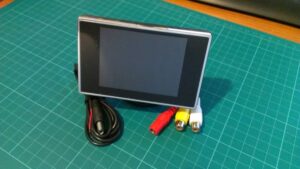
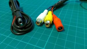
The screen accepts a composite video signal and is powered from 12V. You need to provide your own power supply and composite lead to connect to the Pi. I had both of these parts in my box of spare “stuff”. I used a 12V 2A power supply that came with an external hard drive as it had the correct power plug on it.
Powering from 5V
The device is sold as a reversing camera screen for a car so it is not surprising that it is designed to be powered from 12V. In the world of the Raspberry Pi 5V is sometimes a more convenient voltage to be working and it is possible to modify/hack this device to run from 5V. This procedure is detailed in the RaspberryPi.org forum thread, Modifying a 3.5″ car display for USB power.
Making the console text larger
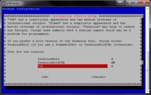
The text on the screen is very small and barely readable. This can be improved by increasing the font size of the console text. To do this run this command :
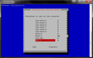
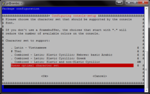
sudo dpkg-reconfigure console-setup
Then using the arrow and enter keys select the following options :
UTF-8
VGA
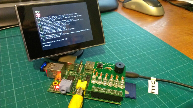
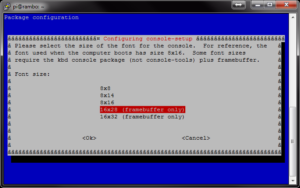 Wait a few seconds and the console text should change. It is now much easier to read on the 3.5 inch LCD screen.

18 Comments
Looks great. I was worried that the text might be a bit small but you look to have overcome this. Definitely adding this to the TODO list. Rich
Did you set values for sdtv_mode, adtv_aspect, overscan_disable, framebuffer_width, framsbuffer_height, overscan_left (right, top, bottom), and then comment all about HDMI setting in the config.txt ?
I did,
https://docs.google.com/open?id=0B0T91wB3ITStME1WYVFDN2JKYVE
the 4.3 inch TFT-LCD has resoultion 480*272.
How ablout your LXDE desktop ? What does it look like ?
thanks,
what settings did you use pls to get the image so clear
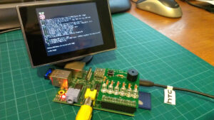
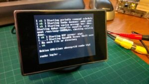
The first photo is just the screen plugged into the Pi with the default Raspbian image. The console-setup screenshots were taken using Putty on my Pc as they weren’t clear enough to follow on the 3.5inch screen itself. The last photo shows the increased font size due to the console-setup tweaks.
That is nice…think I need one now!
I can imagine having this showing weather, news, server stats, TV listings, a webpage, photos, notifications…all sorts
The resolution isn’t great but if you put a sensible amount of data on the screen then it could be great.
Got a link to the place you bought the screen from?
The eBay seller is called obd2diag. Search for “car rearview monitor”.
Is it possible to use this with the P5 header and 5v hack to power the pi and screen from one source or would I overload something? I have a handy 2.5a adapter around somewhere…
The screen can draw 300-400mA and that might be a bit much to draw direct from the 5V pins. It’s probably better to power the screen direct from the power supply at the same time as the Pi. This might require a bit of creative wiring but it wouldn’t put an unnecessary load on the Pi.
Hi Matt,
I love your sentence: “I had no idea what I was going to use it for but decided to worry about that another time.”
Great! LOL, ROFL
Technical enthusiasm must be just so. I often “decide” like you!
My opinion: you are running one of the best blogs to raspberry.
Martin
Hello,
it is working without the cameras?
I try to connect the power, but i don’t have a camera for now.
But there is no signal on the screen?
I have the same lcd screen but for some reason I cannot get this to work. I have tried everything. I know the wiring can be changed on different wires and I’ve switched the wires in every possible combination but no luck. Is there something that I am missing?
Ok! Finally I have figured it out. If you are in the same position I was then follow these steps.
1. Connect your keyboard and TV to the Pi.
2. Insert your SD card.
3. Power on the TV.
4. Power up the Pi and hold down the SHIFT key, until the green LED stops flickering This will force the Pi into recovery mode).
5. If the screen is still blank try pressing the 1, 2 3, 4 keys in succession (one of these will direct the output to the composite video port. You should now have the noobs menu on the screen.
6. If you haven’t already done so choose an OS to install, and reboot. You may need to repeat the above to get back to this menu and continue to the next step.
7. Once you have an OS installed you will need to edit the config file (there is a link on the noobs menu) to select your TV type. Look for this line:
#sdtv_mode=0
remove the leading # and change the number at the end to one of the following:
based on your TV type
sdtv_mode=0 # Normal NTSC
sdtv_mode=1 # Japanese version of NTSC – no pedestal
sdtv_mode=2 # Normal PAL
sdtv_mode=3 # Brazilian version of PAL – 525/60 rather than 625/50, different subcarrier
8. Add the following line to the file:
hdmi_ignore_hotplug=1
9. Make sure that the following line
hdmi_force_hotplug=1
is commented out (has a # at the start of the line).
10.Press the TAB key.
11. Click OK
12. Then hit the ESC key and let the Pi reboot.
Reference and more details can be found here.
https://bhavyanshu.me/tutorials/force-raspberry-pi-output-to-composite-video-instead-of-hdmi/03/03/2014/
I might get one of these, just 1 question; is it backlit (or lit at all for that matter). Thank you very much for any help.
Unfortunately I’ve broken both of mine trying to convert them to run on 5V but yes, they had a backlight.
Theres an 8pin chip nestled between some silver caps. Pull the datasheet on it to find the pins, on mine i was interested in pin 3/4. Take your heatgun and pull that chip off, or carefully use iron to pull chip off without ripping traces. Bridge pins 3/4 with solder. Now you can hook up 5v to the original 12v input and get picture. Additionally if you look at the example designs for the chip you can see there are some further components no longer needed. Leaving the chip on was not sufficient in my case, bridging the pins for VIN and VOUT would cause a bit too high for comfort power draw ;).
Hello!
I realize that I’m ten years late in commenting here but: I found my display, discounted because Adafruit had discontinued it, I used your instructions via your blog which I had found earlier on, mostly because there’s also good advice elsewhere on it. However the command string, #sudo dpkg-reconfigure console-setup in fact also alllows for the device to choose its own font, there I found that there are other settings available. So I’d set the numbers to match the device I’m using. For the Pi1b it was 8×13, (even though that’s not a FB one), for the PiZero I think I chose the 6×13 one which is a FB one.