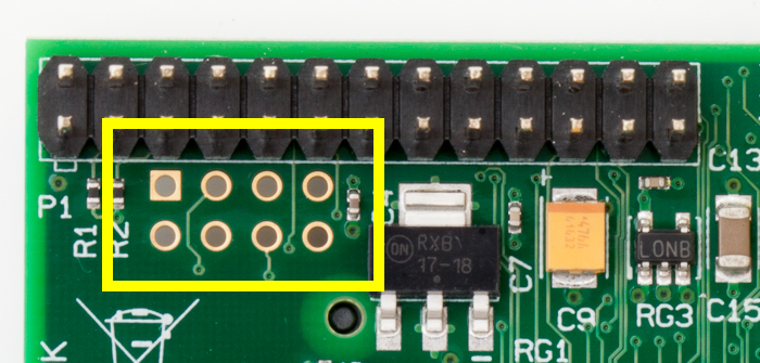
The Raspberry Pi Revision 2.0 introduced a new header to the PCB. This header is called P5 and consists of 8 pins. It is located directly underneath the standard 26 way P1 GPIO header.
It was intended that this header is populated on the underside of the PCB so any connectors or cables do not interfere with the P1 header. Pin 1 has a square pad whereas the other 7 have circular pads.
The P5 pins provide :
- +5V, 3V3 and Ground
- GPIO28
- GPIO29
- GPIO30
- GPIO31
Here are some photos showing the location of the P5 header in relation to the 26 way P1 header :
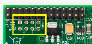
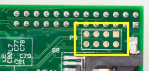
 Here is the pin-out of the P5 header where the square pad is always Pin 1 and Pin 8 is always in the opposite corner :
- +5V
- +3V3
- GPIO28
- GPIO29
- GPIO30
- GPIO31
- Ground
- Ground
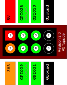 When viewing the underside of the board the layout is mirrored but Pin 1 is still marked with a square pad and Pin 8 is always in the opposite corner.
This header is unpopulated to use it you need to solder your own pin header to the board. The intention is that you would solder a pin header to the underside of the board to avoid getting in the way of P1 and the other headers on the topside.
This is why P5 is labelled on the underside of the PCB but how you solder bits to the board is ultimately your decision based on your requirements.
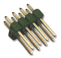 To the right is a photo of the header you need to solder to the PCB. It is a 0.1 inch pitch, 2×4 Pin Header. It may also be described as “8 way” rather than “2×4”. These cost less than £1/$1.

7 Comments
Could have been pretty to see this connector with the i2c bus but anyway, good job!
I may update it to include the i2c info at a later date. At the moment I don’t know much about i2c so I have tended to avoid going into any detail. At some point I’ll get an LCD screen with an i2c interface and have a play with that.
Hey dude,
Did you ever solder anything into this and try it for real?
I only probed the PCB pads with a multimeter. No soldering yet … but now the Welsh 256MB model is a collector’s item I may not subject it to any soldering!
Hey Matt, many thanks for this post!
I’ve just burn out the SDA pin on GPIO because n00bness and I was going to buy a new RaspberryPi, I owe you 25$!
Keep up with the good work man
Pingback: irrigaPi - irrigare il giardino con lo smartphone (o via web) grazie ad un Raspberry Pi - Alessandro GrechiAlessandro Grechi
Im about to make use of the P5, gonna make a small little board with an i2c rtc (ds1307) with an LED for sqw_out and a ds1621, i2c thermostat with pretty high resolution, with its output pin connected to one of the GPIO, an atTINY85 for its ADC (connected over i2c, they run fine on 3v3), and of course a battery. the atTINY85 will be able to measure the level of the battery, the pi 5v source and 3v3 source. might add a tiny buzzer in there connected to a GPIO of the pi or attiny.
Anyway, while doing the research for what id need to implement, it looks like getting i2c on the p5 requires sending some commands to enable it on p5, otherwise it is on s5. this link describes why and how: http://www.raspberrypi.org/forums/viewtopic.php?f=44&t=33092