Following on from my article about controlling a 16×2 LCD module with Python and a Raspberry Pi I decided to make a few enhancements. These included :
- Adding a 10Kohm variable resistor to adjust the contrast
- Adding a 5Kohm variable resistor to adjust the backlight brightness
- Adding a transistor to allow the backlight to be switched on and off
- Allowing left, centred and right justified text
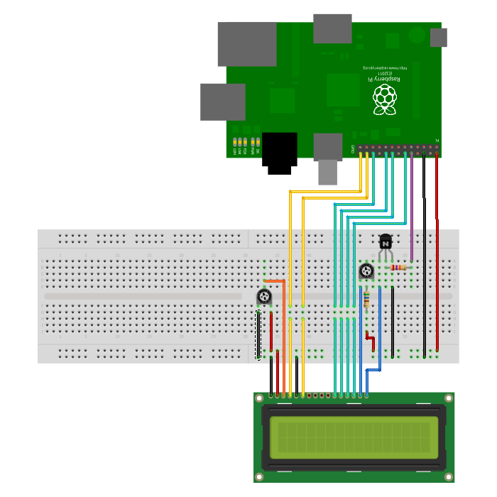
The updated breadboard looks like this :
Contrast Adjustment
Pin 3 is now given a voltage of between 0V and 5V via the middle pin of a 10Kohm trimming pot so that the display contrast can be adjusted.
Backlight Brightness and Switching
 Pin 15/16 are in series with a 560ohm and 2Kohm trimming pot via an NPN transitor (BC547, BC548 or equivalent) which is activated by an additional GPIO connection. The LCD backlight is treated in exactly the same way I switch standard LEDs in my previous Control LED Using GPIO Output Pin article. Using a fixed resistance ensures the resistance can never be adjusted below 560ohm which protects the backlight if you set the trimming pot to zero ohms. The base of the transistor is wired to an additional GPIO pin via a 27Kohm resistor.
Text Justification
The function “lcd_string” has been modified to accept a second parameter. This parameter takes the value 1, 2 or 3 and determines how the text is displayed on the screen.
Python
Here is the updated code :
#!/usr/bin/python
#--------------------------------------
#    ___  ___  _ ____
#   / _ \/ _ \(_) __/__  __ __
#  / , _/ ___/ /\ \/ _ \/ // /
# /_/|_/_/  /_/___/ .__/\_, /
#                /_/   /___/
#
#  lcd_16x2.py
#  16x2 LCD Test Script with
#  backlight control and text justification
#
# Author : Matt Hawkins
# Date   : 06/04/2015
#
# https://www.raspberrypi-spy.co.uk/
#
#--------------------------------------

# The wiring for the LCD is as follows:
# 1 : GND
# 2 : 5V
# 3 : Contrast (0-5V)*
# 4 : RS (Register Select)
# 5 : R/W (Read Write)       - GROUND THIS PIN
# 6 : Enable or Strobe
# 7 : Data Bit 0             - NOT USED
# 8 : Data Bit 1             - NOT USED
# 9 : Data Bit 2             - NOT USED
# 10: Data Bit 3             - NOT USED
# 11: Data Bit 4
# 12: Data Bit 5
# 13: Data Bit 6
# 14: Data Bit 7
# 15: LCD Backlight +5V**
# 16: LCD Backlight GND

#import
import RPi.GPIO as GPIO
import time

# Define GPIO to LCD mapping
LCD_RS = 7
LCD_E  = 8
LCD_D4 = 25
LCD_D5 = 24
LCD_D6 = 23
LCD_D7 = 18
LED_ON = 15

# Define some device constants
LCD_WIDTH = 16    # Maximum characters per line
LCD_CHR = True
LCD_CMD = False

LCD_LINE_1 = 0x80 # LCD RAM address for the 1st line
LCD_LINE_2 = 0xC0 # LCD RAM address for the 2nd line

# Timing constants
E_PULSE = 0.0005
E_DELAY = 0.0005

def main():
  # Main program block

  GPIO.setwarnings(False)
  GPIO.setmode(GPIO.BCM)       # Use BCM GPIO numbers
  GPIO.setup(LCD_E, GPIO.OUT)  # E
  GPIO.setup(LCD_RS, GPIO.OUT) # RS
  GPIO.setup(LCD_D4, GPIO.OUT) # DB4
  GPIO.setup(LCD_D5, GPIO.OUT) # DB5
  GPIO.setup(LCD_D6, GPIO.OUT) # DB6
  GPIO.setup(LCD_D7, GPIO.OUT) # DB7
  GPIO.setup(LED_ON, GPIO.OUT) # Backlight enable

  # Initialise display
  lcd_init()

  # Toggle backlight on-off-on
  lcd_backlight(True)
  time.sleep(0.5)
  lcd_backlight(False)
  time.sleep(0.5)
  lcd_backlight(True)
  time.sleep(0.5)

  while True:

    # Send some centred text
    lcd_string("Rasbperry Pi",LCD_LINE_1,2)
    lcd_string("16x2 LCD Test",LCD_LINE_2,2)

    time.sleep(3) # 3 second delay

    # Send some left justified text
    lcd_string("1234567890123456",LCD_LINE_1,1)
    lcd_string("abcdefghijklmnop",LCD_LINE_2,1)

    time.sleep(3) # 3 second delay

    # Send some right justified text
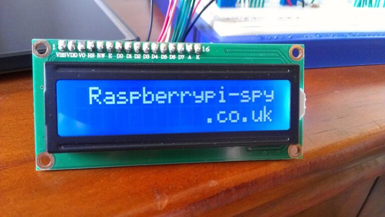
    lcd_string("Raspberrypi-spy",LCD_LINE_1,3)
    lcd_string(".co.uk",LCD_LINE_2,3)

    time.sleep(3) # 20 second delay

    # Send some centred text
    lcd_string("Follow me on",LCD_LINE_1,2)
    lcd_string("Twitter @RPiSpy",LCD_LINE_2,2)

    time.sleep(3)

def lcd_init():
  # Initialise display
  lcd_byte(0x33,LCD_CMD) # 110011 Initialise
  lcd_byte(0x32,LCD_CMD) # 110010 Initialise
  lcd_byte(0x06,LCD_CMD) # 000110 Cursor move direction
  lcd_byte(0x0C,LCD_CMD) # 001100 Display On,Cursor Off, Blink Off
  lcd_byte(0x28,LCD_CMD) # 101000 Data length, number of lines, font size
  lcd_byte(0x01,LCD_CMD) # 000001 Clear display
  time.sleep(E_DELAY)

def lcd_byte(bits, mode):
  # Send byte to data pins
  # bits = data
  # mode = True  for character
  #        False for command

  GPIO.output(LCD_RS, mode) # RS

  # High bits
  GPIO.output(LCD_D4, False)
  GPIO.output(LCD_D5, False)
  GPIO.output(LCD_D6, False)
  GPIO.output(LCD_D7, False)
  if bits&0x10==0x10:
    GPIO.output(LCD_D4, True)
  if bits&0x20==0x20:
    GPIO.output(LCD_D5, True)
  if bits&0x40==0x40:
    GPIO.output(LCD_D6, True)
  if bits&0x80==0x80:
    GPIO.output(LCD_D7, True)

  # Toggle 'Enable' pin
  lcd_toggle_enable()

  # Low bits
  GPIO.output(LCD_D4, False)
  GPIO.output(LCD_D5, False)
  GPIO.output(LCD_D6, False)
  GPIO.output(LCD_D7, False)
  if bits&0x01==0x01:
    GPIO.output(LCD_D4, True)
  if bits&0x02==0x02:
    GPIO.output(LCD_D5, True)
  if bits&0x04==0x04:
    GPIO.output(LCD_D6, True)
  if bits&0x08==0x08:
    GPIO.output(LCD_D7, True)

  # Toggle 'Enable' pin
  lcd_toggle_enable()

def lcd_toggle_enable():
  # Toggle enable
  time.sleep(E_DELAY)
  GPIO.output(LCD_E, True)
  time.sleep(E_PULSE)
  GPIO.output(LCD_E, False)
  time.sleep(E_DELAY)

def lcd_string(message,line,style):
  # Send string to display
  # style=1 Left justified
  # style=2 Centred
  # style=3 Right justified

  if style==1:
    message = message.ljust(LCD_WIDTH," ")
  elif style==2:
    message = message.center(LCD_WIDTH," ")
  elif style==3:
    message = message.rjust(LCD_WIDTH," ")

  lcd_byte(line, LCD_CMD)

  for i in range(LCD_WIDTH):
    lcd_byte(ord(message[i]),LCD_CHR)

def lcd_backlight(flag):
  # Toggle backlight on-off-on
  GPIO.output(LED_ON, flag)

if __name__ == '__main__':

  try:
    main()
  except KeyboardInterrupt:
    pass
  finally:
    lcd_byte(0x01, LCD_CMD)
    lcd_string("Goodbye!",LCD_LINE_1,2)
    GPIO.cleanup()
This script can be downloaded using this link or directly to your Pi using the following command :
wget https://bitbucket.org/MattHawkinsUK/rpispy-misc/raw/master/python/lcd_16x2_backlight.py
Remember to update the constants at the top of the script to match the GPIO signals you are using on your Pi. As always these GPIO references are the Broadcom signal names as described in my GPIO header article.
Take a look at my other LCD Screen related posts which include details of the 20×4 version of the screen used in this post.


12 Comments
Yo only me again. I’ve got to pop into maplins again to order the correct new parts.
1. 10Kohm variable resistor
2. 5Kohm variable resistor
3. NPN transitor
Thanks dude
Hi
Great article, just one question. Which NPN transitor did you use?
Looking in Maplin there are quite a few to choose from with different characteristics e.g. 2N5551, BC635 etc.
Cheers
Hey Mark they are BC547
Cheers
First of all: Thanks for the great tutorial! Thanks to this I have a nice new clock with date and everything. I was confident I could somehow pull it off myself but your article/code solved a lot of mysteries that would have made my code extremely complicated (I didn’t notice the HD44780 characters were exactly the ascii value and stuff like that…).
I tried to understand all that happens but the lcd_init() is still confusing me a bit. I don’t know if I just read the HD44780 documentation completely wrong. I can follow the initialisation that is described here:
http://www.protostack.com/blog/2010/03/character-lcd-displays-part-1/
Could you elaborate a bit what the single calls do?
I’m currently trying to read an rss feed and send it to the lcd. I wanted to use the built in shift function, but if I use one line for the feed and the other one for the time I have to manipulate the rss line in the software itself and cannot send out just one char after the other, right?
The program runs, but the Left – Right – Center isn’t working.
And I’ve spent 2 hours trying to figure out what’s wrong.
3 is aligning Center, and 1 & 2 are aligning Left
Add some print statements to the lcd_string function. Confirm the “message” and “LCD_WIDTH” variables are correct and the IF statement is calling the correct branch.
I’m using a 2N3904. I had to drop to a 1K to be able to see the ON/OFF state.
27K was barely visible.
Pingback: 20×4 LCD Module Control Using Python | Raspberry Pi Spy
Good project! Thanks for sharing it.
Very good tutorial, thanks! One question: Here, the brightness of the display is regulated with a variable resistor.
I’m looking for a solution where the brightness is adjusted *automatically* in function of the surrounding light. So, a light sensitive resistor should give me a value for the surrounding light. But how can I control the brightness via the raspberry pi?
Here is an example of controlling the brightness of an LED :
https://gpiozero.readthedocs.io/en/stable/recipes.html#led-with-variable-brightness
LCD pin 16 will still go to ground but LCD Pin 15 will go via a resistor (minimum 100ohm) to GPIO17 (or anyother GPIO you want to use).