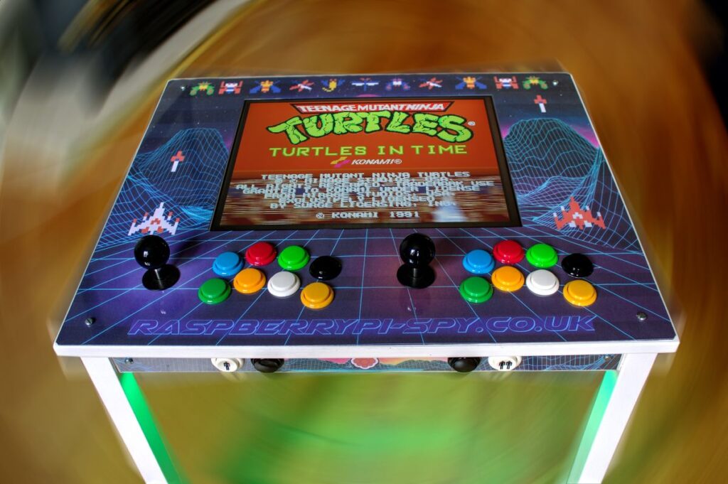
In a previous post I introduced my Raspberry Pi arcade table built with an IKEA table and a Raspberry Pi 3 running RetroPie. I’m sure people might be interested in how I made it so I’ll go into a little bit more detail here.
How I approached this project was heavily influenced by my own abilities, what tools I had available and what parts I was able to obtain or buy. For these reasons other people’s arcade table projects will look different. Hopefully this article will at least act as some inspiration for others even if it is not copied exactly.
I have a arranged the sections in the rough order in which I acquired or thought about the parts.
Raspberry Pi Arcade Parts List
Here’s a list of the components I used :
- IKEA “Gulliver” wooden table
- 2 arcade joysticks
- 2 USB controller boards
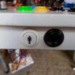
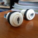
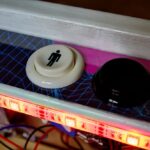
- 2 buttons with 1/2 player symbols
- 2 “coin” buttons
- 16 arcade buttons
- 1 LCD monitor + power cable + VGA cable
- 1 HDMI-to-VGA adapter
- 1 USB powered speaker
- 1 3.5mm audio cable
- 1 5m 1-gang power cable
- 1 2-gang + 2 USB port power adapter
- 1 5V microUSB power supply
- 1 sheet of clear perspex (from IKEA “FISKBO” picture frame)
- random collection of screws and cable ties.
Tools
- Jigsaw
- Cordless drill
- 30mm hole cutter bit
- Craft knife
- Paint
The Table
The table is an IKEA “GULLIVER” kids table which we had passed onto a friend but retrieved when it was no longer required. Unlike most other IKEA arcade projects this table has a solid 16mm MDF top measuring 50x59cm. Taking into account the under-frame this gave a working area of 42x51cm. The legs are attached using metal brackets so it is nice and sturdy. You can use almost any table you just need to ensure there is enough space to mount the monitor and buttons.
The IKEA “KRITTER” 59×50 cm table looks very similar to the “GULLIVER”.
The Monitor
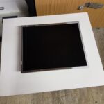
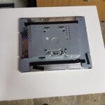
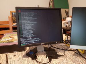 The monitor is a DELL E177 17″ display which I was lucky enough to buy locally for £5. Removing the front bezel and rear shell was fairly straight forward and I used a YouTube video as a starting point. I removed the small PCB with the buttons on it and found I didn’t need them again so I didn’t reattach. The “naked” monitor is a nice rectangular block giving plenty of mounting options. This monitor only has a VGA input so I used an HDMI-to-VGA adapter to connect it to the Pi.
To keep the wiring tidy I bought shorter power and VGA cables to replace the standard cables that came with the monitor.
Layout
Using LibreOffice Draw I created a 1:1 scale diagram of the table. I was careful to make sure that the area I was going to drill/cut didn’t interfere with the structure underneath holding the legs on. I also thought a bit about how the monitor cables and plugs would be routed so they didn’t get in the way of the metal brackets.
The diagram showed me where to cut the monitor hole and the holes for the joystick and arcade buttons.
Arcade Buttons & Joysticks
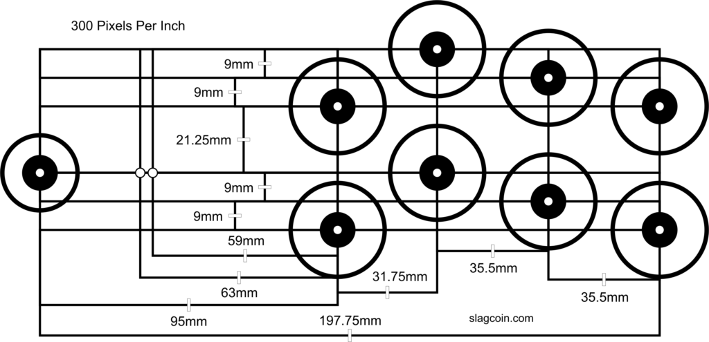
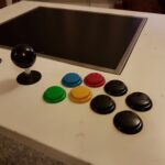
After much deliberation I decided that although I didn’t need 8 buttons per player I didn’t want to regret adding too few. So I went for 8 buttons and 1 joystick per player. Having used RetroPie on my TV I also wanted 4 additional buttons to use as “Select” and “Start” options for SNES games. These would also act as Player/Coin buttons in MAME games. So in total I had 16 buttons + 4 buttons + 2 joysticks. I ordered these from eBay along with two buttons with “player” symbols on them. The button sets also came with USB controller boards that everything plugged into. Once these arrived I knew how big the holes needed to be and I finalised the layout diagram.
I picked a button layout from Slagcoin that looked like this :
Testing
I setup the Pi, the monitor and the arcade buttons to check everything worked OK. This was the point I knew my hardware was OK and it was worth proceeding.
Cutting, Drilling & Painting
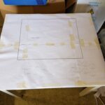
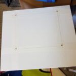
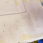
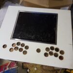
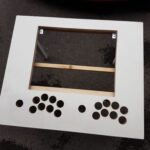
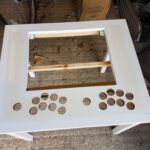
Armed with a printout of my final layout I stuck it on the table and cut the monitor hole. I drilled holes in the corners and used a jigsaw to cut the straight lines in between. To ensure straight cuts I clamped some wood in place to use as a guide for the jigsaw foot. I knew I would be placing some sort of graphic over the top so the cuts needed to be good but not perfect.
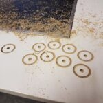
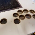
I used a 30mm drill bit to cut the 20 holes for the buttons and 2 for the joysticks. Although a 28mm bit would have been more suitable in places went with a “one size fits all” approach as it saved me buying a second bit.
Mounting the Monitor
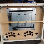
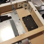
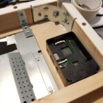
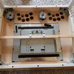
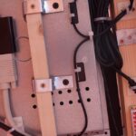
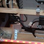
With the holes cut I had to do a bit of filing and sanding to get the monitor to fit in the hole. Then I used a wooden banton along the back to hold it in place. This banton was held in place with some horizontal screws and some metal brackets screwed into the VESA mount holes in the monitor.
Two additional metal brackets were added to provide a bit more support on the top edge.
During this stage I had to be extra careful to not allow the monitor to fall through the hole until it was secured properly!
The viewing angle of the Dell monitor was much better from the top. So it is actually mounted upside-down. I configured the Pi to flip the image.
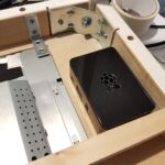
Mounting the Raspberry Pi
The Raspberry Pi 3 was the obvious choice. Any Pi model would be usable but I didn’t want to bother upgrading at a later date. The case was chosen as it was nice quality and easy to screw in place. The Pi and case were donated by RS Components.
Mounting Buttons, Joysticks and Controller Boards
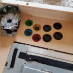
The style of buttons I used allowed them to friction fit in the holes. The joysticks have a metal plate which was screwed into the underside of the table top.
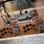
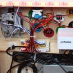
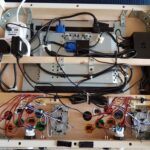
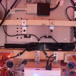
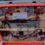
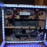
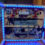
An additional wooden baton was added to further hold the monitor in place but also give me something to screw the controller boards to. The buttons and joysticks were then wired up to the controller boards which in turn were connected to the Pi’s on-board USB ports. The controller board came with all the cables required to connect the joysticks and buttons.
The Power Supply
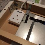
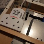
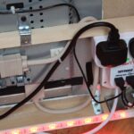
Powering everything required some thought. Originally I was going to fit a 4-way extension cable but in the end went for a standard 5 metre 1-gang mains extension cable with a 2-gang splitter. The splitter included two 5V USB sockets. These USB ports would probably not power the Pi directly so I used a proper 5V power supply for that. The second socket was used for the monitor power cable.
The 1-gang socket case is screwed into place. I had to drill 4 holes through the case in order to mount it.
*NOTE* this is the one bit of hacking I did to something involving mains electricity. Proceed with caution! I didn’t want to electrocute myself, my child or any of his friends at a later date. It’s this reason I didn’t worry about customising mains cabling or adding power switches etc.
The Speaker
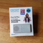
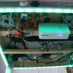
Sound is actually one of the more challenging considerations if you want to keep costs down. I looked for some cheap PC speakers but ended up buying a small “Bluetooth” amplified speaker with an AUX input. It is powered via one the USB sockets on the Energiser power splitter. The 3.5mm jack connects to the analogue output on the Pi. Being nice and square it was easier to mount this on a bracket underneath the table with sticky pads.
The Perspex and Graphics
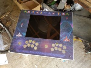
Using my LibreOffice Draw template I played around with some graphics. It’s not easy as cool pictures are often ruined once you remove the hole for the monitor.
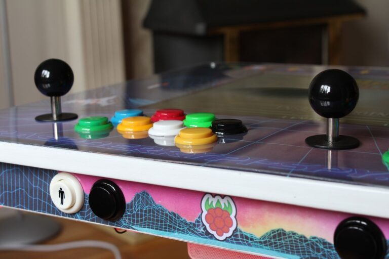
I settled on a generic 80s looking virtual landscape and decorated with sprites from Galaga.
Acquiring a piece of cheap perspex was a challenge. In the end I bought a “FISKBO” 50x70cm photo frame from IKEA (£5) and used that. It’s thinner than I would like but does the job. Rather than use my paper template I used the table and a Sharpie to mark the position of the holes on the plastic before carefully drilling 30mm holes. Luckily my careful approach resulted in 18 holes in the perspex without any cracks! I also created a strip to cover the front edge with 4 holes.
Update : Lots of people have asked about the graphic files I used. They can be downloaded from my Google Drive Folder. They may or may not be useful to you and a lot will depend on what printing facilities you have. In many cases it would be easier to create your own template using whatever application you are most familiar with.
The Multi-coloured LED Lights
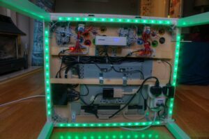 These were a bit of an after-thought but I knew they would be easy to mount and would run from the 2nd USB socket I had available. They were £10 from eBay and came with a remote control. I did have to shorten the lengths by slicing them at the correct points and re-soldering the connectors on the end. There are plenty of YouTube videos that explain how to cut LED strip lights. The remote can be used to change the colour which adds a bit of atmosphere to the whole table and make it just a little bit more impressive to other people. You can pick a colour that suits the game you are playing. (Green for Ninja Turtles obviously)
General Wiring
To avoid anyone snagging cables during use I tried to make sure all cables were secured out of the way. I used a selection of cable-ties and plastic cable-tie mounts. Where possible these mounts were screwed in place as sticky pads always fail at some point.
Pi/RetroPie Config
I’m not going to get into the installation or configuration of RetroPie but two tweaks I had to make relating to this hardware setup are worth mentioning.
- The first was telling the Pi to rotate the screen to compensate for the monitor being mounted upside-down (see display rotation tutorial)
- The second was forcing the Pi to output audio on the 3.5mm jack and not via HDMI (see force 3.5mm audio tutorial)
Component Prices and Total Cost
The total cost for my Raspberry Pi arcade table was £150 ($200). Here is the final costings for this project and I’ve split it into three sections.
| Cost | Supplier | |
|---|---|---|
| Raspberry Pi Parts | ||
| Raspberry Pi 3 | £39.59 | RS (donated) |
| Raspberry Pi Case | £5.39 | RS (donated) |
| Power supply | £7.80 | RS (donated) |
| 16GB microSD card | £9.00 | Amazon |
| sub-total | £61.78 | |
| Project Specific Parts | ||
| IKEA Gullilver Table | £0.00 | Local Facebook selling group |
| 17inch monitor | £5.00 | Facebook Marketplace |
| VGA cable | £0.00 | Came with monitor |
| IEC “kettle” power cable | £0.00 | Came with monitor |
| HDMI to VGA converter | £2.40 | eBay |
| Portable speaker | £6.99 | B&M Bargains |
| Zero delay board + joystick and arcade buttons | £17.40 | eBay |
| Zero delay board + joystick and arcade buttons | £17.40 | eBay |
| 5m single socket extension cable | £4.99 | B&M Bargains |
| 2-socket extension block with 2 USB outputs | £8.99 | B&M Bargains |
| Misc screws | £0.00 | My workshop |
| Scrap wood | £0.00 | My workshop |
| sub-total | £63.17 | |
| Optional Upgrades | ||
| 1 & 2 player buttons | £6.99 | eBay |
| Spade terminals for player buttons | £1.80 | eBay |
| Multicolour LED strip light kit | £9.39 | eBay |
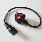
| 0.5m IEC “kettle” cable | £3.39 | eBay |
| 0.5m VGA cable | £3.00 | eBay |
| sub-total | £24.57 | |
| £149.52 |
The cost can be decreased if you already have items available or you ignore the “optional” upgrades. The monitor and Raspberry Pi are likely to be the most expensive items. You could also choose to use a Pi 1 or Pi 2.
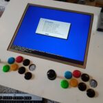
Arcade Table Photos
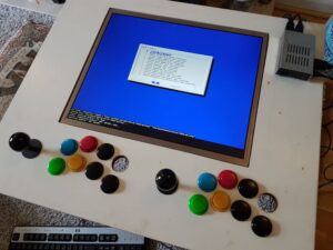
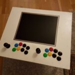
Here are some additional photos :
Final Thoughts
I was really pleased with how this turned out. The only issues I’ve had over the last few months are with the speaker coming unstuck from its bracket so I need to take a look at a better mounting option for that.
I’ve created a video slideshow of the photos for people who prefer watching to reading :
Raspberry Pi arcade projects are extremely popular so give it a try. You can build a retro gaming system first and then decide how to build a cabinet or table afterwards.

25 Comments
Having made an original “LACK” table 1 player version this 2 player one looks ace! Checking IKEA this table looks like a “KRITTER” that’s 59x50x50cm, is that the one? The “GULLIVER” seems to be a baby changing table now.
Love the light strip underneath although I doubt I’d ever keep the wires that tidy 🙂
The “GULLIVER” range doesn’t include the table anymore. But the “KRITTER” table seems to very similar. I think it has the same metal corner brackets underneath.
what’s the photo frame called I cant seem to pick it out
The frame is a “FISKBO” 50x70cm :
Hi mat i have taken the monitor part and I still have the pcb got the buttons attached as I am new to this I was wounding will the monitor still power up when attached to raspberry pi and plugged in as I don’t have a clue lol. Great build it’s inspired me to make my own cheers
I carefully removed the PCB and planned to fit it after I mounted the monitor. What I found was that the monitor worked fine without it and I didn’t need to use them. So my table just has the bare monitor. It powers up OK and the default brightness and contrast etc looks fine.
Wonderful project, is it possible that you share your diagram? Thank you and happy new year 😉
Can you post/share a link to your template file?
I’ve added a link to my Google Drive folder. The LibreOffice file has layers in it that can be switched on and off.
Nice project. I may try to build a more stand-up version.
BTW, when cutting or hole sawing thin plastic that you’re worried about cracking if the teeth of the saw grab and bite, I find it helps to run the blade (or with a hole saw, the drill) in reverse. This way you’re basically cutting through without the chance of the aggressive grabbing and snapping/cracking the plastic.
Good tip. It’s also worth doing it in short bursts so the heat build-up doesn’t start melting the plastic.
Do you think i can follow this as a tutorial, or do you think the wiring is too complex, thanks
It is really just power, monitor and two USB controllers. You could buy 1 USB controller and just try it with your Pi. No need to worry about mounting anything. Just get it working on a desk.
Cool thanks, do you think the joysticks/buttons would work with Gameboy games or any of the other emulators other than SNES and MAME
They work fine with Gameboy/Gameboy Advance/Gameboy Color games as that is really just a joystick and the A/B buttons. It only starts getting complicated with consoles that had multiple directional controls such as the Playstation 1.
Love this project! Not sure if this is a silly question or not but what did you print the graphic file onto? Is it just paper overlaid with the Perspex?
Luckily I had access to a large A0 plotter. The paper is very similar to standard laser jet paper. Without that I might have needed to order a print from a poster company. That might give a better result as the current printout isn’t quite as bold as a glossy magazine style process.
Thank you for the tutorial. My kids (5 & 9) and I are looking for a summer project and this looks perfect. We are new to coding, would you be able to point me in the right direction in terms for the programming it would need?
The first step is creating an SD card with “retropie”. Then the next step is acquiring and adding game ROMS. This doesn’t really require coding but will take some time to research. You are better browsing the guides on the RetroPie site or looking for getting started tutorials on YouTube.
Hi. Was the wired Bluetooth speaker powered by usb? Did you add it to the extension plug usb outputs? Finding my pi is under powered using all usb ports.
I powered the speaker from the mains unit. So the only USB devices plugged directly into the Pi were the two arcade controller boards.
Hi Matt
Great build! I’m currently building one based on your guide.
I was wondering what the parts are called that you used to hold the monitor to the table and the baton? And the screw types if possible?
They are “flat metal brackets” with pre-drilled holes that I bent into shape. The screw holes will take 4-5mm screws with the length being determined by the wood you are screwing into. If you go into a hardware store you should be able to find something similar.
I had so much fun building one of these a few years back that well, I built a few… Check out the below to be taken all the way back to the 1980s! ?
https://www.instagram.com/playble.fun/
Love the design, thanks for the inspiration and layouts! Guess I’m building my own now 🙂 Of course rpi4 now with lakka and as the monitor I just picked up has an extenral power supply maybe the whole table can be low-power….
Also thanks for the idea of the poster print for the background!