LEDs, buzzers and switches are the most common items people attempt to interface to their Raspberry Pi’s. Something I found in eBay that is a little bit different is an ultrasonic measurement module. This allows you to measure the distance to the nearest wall or solid object. The modules are easy to buy, cheap and relatively straight forward to interface to the GPIO header.
So here is some information on my experiments with an Ultrasonic measurement module and Python. In future projects I can see these modules being a great way to add some intelligence to a Pi powered robot or car.
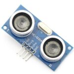
 The HC-SR04 module cost approximately £3 ($5) and is the size of a box of matches. The two transducers give it a distinctive appearance. It is designed to be powered by 5V, has 1 input pin and 1 output pin. The module works by sending an ultrasonic pulse into the air and measuring the time it takes to bounce back. This value can then be used to calculate the distance the pulse travelled.
Connecting To The Pi
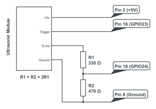
Powering the module is easy. Just connect the +5V and Ground pins to Pin 2 and Pin 6 on the Pi’s GPIO header.
The input pin on the module is called the “trigger” as it is used to trigger the sending of the ultrasonic pulse. Ideally it wants a 5V signal but it works just fine with a 3.3V signal from the GPIO. So I connected the trigger directly to Pin 16 (GPIO23) on my GPIO header.
You can use any GPIO pins you like on your RPi but you will need to note the references and amend your Python script accordingly.
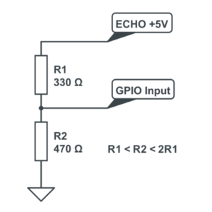
 The module’s output is called the “echo” and needs a bit more thought. The output pin is low (0V) until the module has taken its distance measurement. It then sets this pin high (+5V) for the same amount of time that it took the pulse to return. So our script needs to measure the time this pin stays high. The module uses a +5V level for a “high” but this is too high for the inputs on the GPIO header which only like 3.3V. In order to ensure the Pi only gets hit with 3.3V we can use a basic voltage divider. This is formed with two resistors.
If R1 and R2 are the same then the voltage is split in half. This would give us 2.5V. If R2 is twice the value of R1 then we get 3.33V which is fine. So ideally you want R2 to be between R1 and R1 x 2. In my example circuit I used 330 and 470 ohm resistors. An alternative would be to use 1K and 1K5 values.
Here is a diagram of my final circuit. I chose GPIO23 and GPIO24 but you can use any of the 17 available GPIO pins on the GPIO header. Just remember to update the script.

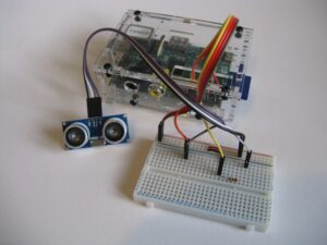
Here is a photo of my circuit. I used a small piece of breadboard and some male-to-female jumper cables.

Python Script
Now for the script to actually take some measurements. In this example I am using Python. Why Python? It’s my favourite language on the Pi so I tend to use it for all my experiments but the technique here can easily be applied to C.
You can either download the script directly using this link or via the command line on the Pi using :
wget https://bitbucket.org/MattHawkinsUK/rpispy-misc/raw/master/python/ultrasonic_1.py
This can then be run using :
sudo python ultrasonic_1.py
Speed of Sound
The calculation that is used to find the distance relies on the speed of sound. This varies with temperature. The scripts calculate the correct value to use based on a pre-defined temperature. You can change this value if required or perhaps measure it dynamically using a temperature sensor.
Photos
Here are some photos of my ultrasonic sensor connected to Raspberry Pi via the GPIO header :
Accuracy
Here are some points about accuracy :
- The accuracy of the distance measurement is dependent on timing. Python under Linux is not ideal for precise timing but for general messing about it will work OK. To improve accuracy you would need to start looking at using C instead.
- When the GPIOs are configured the module needs some time before it is ready to take its first reading so I added a 0.5 second delay to the start of the script.
- The transducers have a wide angle of sensitivity. In a cluttered environment you may get shorter readings due to objects to the side of the module.
- Measurements work down to about 2cm. Below this limit the results can give strange results.
- If the ultrasonic transducers touch anything the results are unpredictable.
Thanks to this technology I now know that the distance from my desk to the ceiling is 155cm.
Update
If anyone wants to experiment with these devices in C then check out this page :
http://rasathus.blogspot.co.uk/2012/09/ultra-cheap-ultrasonics-with-hy-srf05_27.html
It also includes a comparison between Python and C implementations.
Credits
Thanks to Leroy Milamber for correcting an error in my code.
Related Articles
Here are some of my other articles you might find interesting if you enjoyed this one :

52 Comments
Thanks so much for the post. I received one of these sensors for Christmas!
Excellent! Definitely worth a play. Not sure what I am going to use one for but if I ever make a Pi based vehicle it will almost certainly feature a few of them.
I didn’t see a model number for the sensor mentioned here, but it looks very similar in both appearance and operation to the HY-SRF05’s I played about with.
Whilst I was experimenting with these I managed to persuade Joan on the forums to write a simple C implementation for the HY-SRF05, but it looks like it could be used with yours without modification. If you fancy some experimentation, the code is posted as part of an article here …
http://rasathus.blogspot.co.uk/2012/09/ultra-cheap-ultrasonics-with-hy-srf05_27.html
Mine is labelled SRF04 although my photos seem to have concealed the “4”. Had a look at your page. Great stuff. I’ll add a link from my article to your page for anyone who is interested in working with C.
Thanks for the link. I should probably dig my sensors out and make some time to have another play around with them. It sounds like some of my measurements may have been rather affected by clutter, as they would have been taken from my desk.
Interesting post. Do you really think the timings will be better if you use C? I’ve got one of these too, but was planning to use an Arduino in between the Pi and the sensor because of the accuracy of timing on the Pi.
It was more of a guess but I suspect C would be slightly faster. Although the main source of error I saw was the influence of surrounding surfaces. If the sensor had a wide, clear “tunnel” to the target the accuracy was fairly good. As soon as you get a bit of clutter in the environment the results can be unexpected.
There seems to be a discrepancy between what you describe and your code:
You mention that the module sets ECHO to HIGH (5V) for the amount of time it took the pulse to go and come back…
—quote—
The output pin is low (0V) until the module has taken its distance measurement. It then sets this pin high (+5V) for the same amount of time that it took the pulse to return. So our script needs to measure the time this pin stays high.
—quote—
Your code actually measures the time from the end of the trigger until the end of the HIGH echo…
Based on your module’s description, should it not rather be:
# Send 10us pulse to trigger
GPIO.output(GPIO_TRIGGER, True)
time.sleep(0.00001)
GPIO.output(GPIO_TRIGGER, False)
# measure the time this pin stays high
# start value is the last low for ECHO pin
while GPIO.input(GPIO_ECHO)==0:
start = time.time()
# end value is the last high for ECHO pin
while GPIO.input(GPIO_ECHO)==1:
stop = time.time()
# Calculate pulse length
elapsed = stop-start
and maybe you won’t need the adjustment value.
Thoughts ?
Kind regards
Leroy, you are correct. Not quite sure why I was recording the stop time when I should have been updating the start time while waiting for the pulse to start. I have updated my script and removed the adjustment value. I have quickly tested with my hardware and the adjustment value is no longer needed. Thank you for your helpful comment!
You’re both wrong, unfortunately, significantly wrong.
You don’t put an operating system call (or any other call) in the middle of a loop if you’re trying to time something accurately. You simply spin until the bit changes.
# Get the FIRST HIGH
while GPIO.input(GPIO_ECHO)==0:
~~~~pass
start = time.time()
$ Get the FIRST LOW
while GPIO.input(GPIO_ECHO)==1:
~~~~pass
stop = time.time()
Great stuff. Thanks for the excellent write-up. I was able to interface this to my Pi without any smoke. Thanks for the knowledge of the voltage divider!
How accurate is this sensor? What is the resolution? Can it distinguish between 3 inches and 4 inches, for example? What are the maximum and minimum ranges
it can be used at?
Thanks
It can tell the difference between 3 and 4 inches. The minimum range is probably about 1 inch. I haven’t tried it over longer distances so not quite sure what the maximum is.
Cheapest ultrasonic unit I can find is £14.85!? Any advice? K..
Search eBay for “ultrasonic module”. There should be plenty for £3 including UK sellers.
I had some initial problems with this on a rev2 pi. It was sensing the initial pulse and so returning some very small figures. Looking at the specsheet for this device (mine is a HC-SR04) it suggest a 60ms wait after the trigger to avoid detecting the trigger. That’s an easy fix:
after the
GPIO.output(GPIO_TRIGGER, False)command just addtime.sleep(0.00006)and all works fine.
The specsheet also says it will measure upto 4m, but in reality it is a lot shorter, and using python the distance is not very accurate (within 5cms per meter--ish) it also measures down to about 3cm in my experience.
Thanks for the code though, saved me a huge headache trying to fathom it.
Cant wait to get mine Matt, should be here soon.
Going to be ripping off this articles into a video soon 🙂 Standard reference back to you though 🙂
Hey Matt,
Made this for my upcoming video. Though you might want a copy to update your blog.
https://dl.dropbox.com/u/419255/Raspberry%20PI/Ultrasonic_bb.png
Thanks
Matt
Hey!
Thanks for this great tutorial! One thing that I am having a few issues with! How would I get a continuous display of data? Not just the one value? And also what are the units? CM?
Thanks!
The Raspberry Pi Guy
Hi,
This is excellent article/tutorial.
I have made 20m long UTP cable where on one end was connected sensor, and on other end was raspi (using single wire for connections). Everything is working perfectly (even without delay mentioned in comments by PJ Lucas).
What I have found is problem in code… There is possibility that:
– gpio pin is already in use
– program never gets high or low signal in while loop (happened two times)
For first thing there needs to be checked if gpio is in use, where on second thing I would first calculate how long program would need to do max wait, and than just compare start/end time against that value and exit loop.
My application of this tutorial will be to have sensor on 40m long cable with sensor set down in water well measuring water level (1m over water level aprox, covered with warm plastic to prevent water damage), and raspi would be outside of well in dry place.
Thank you for tutorial and idea how to use raspi.
Hi,
where do you get those tiny voltage dividers from? I couldn’t even find them on amazon!
thanks! great site!
LOS
The voltage divider is just two standard resistors.
This wont work for me. Does not get any echo and therefore loops in line 43/44.
However, if I directly connect the echo pin (no Rs) it gives me results.
Why is that? Can anyone tell me?
P.S:
Minimum Range is ~ 3.0 and maximum is 120
I can only suggest the module you are using isn’t outputting 5V on the echo pin. Is it the same module? Are you powering it from 5V? If it is using a lower voltage the resistors would be feeding the GPIO pin with a voltage that is to low to register as a valid HIGH.
I have a query regarding this. I get a feeling that since the OS running on top of the RPi – Raspbian is not a real-time operating system, the trigger signal from the ultrasonic can be missed on reflection. This can be due to the fact that there are several other processes running in the background of the RPi, and so the echo pin’s reading command can be missed out or done later than when it should have.
I used the module to find out height of people walking under the sensor. I tried implementations on RPi (python code) as well as Arduino. While the Arduino recorded around 10 values on an average for a person walking, the RPi code was only able to record around 4-5 values. This, I presume might be because of the reason I mentioned above. Any thoughts?
hey matt
i used your ultrasonic_2.py program in my project, i want to add beep in my program (means.. it should generate a beep when it calculate a distance or detect obstacle) but i am unable to do so
Pingback: Raspberry Pi – Ultrasonic distance sensor | Paul Görgen
Hi, great tutorial!
How many watts do the resistors have?
They are standard 1/4W resistors.
hello, i want to connect 2 or posibly more ultrasonic sensors to 1 raspberry pi, can you walk me through of what i need? cause im trying to duplicate all the code by this i mean, defining 2 new pins, setting them, basically just duplicating everything, but its not working for me.
Hi,
Thank you for the wonderful write up. Unfortunately, when i try to run it, i get bogus readings.
For example, 12.2 cm distance no matter what object i put in front of it, the only things i changed where the pin assignments
import time

import RPi.GPIO as gpio
gpio.setmode( gpio.BCM )
# setup pin assignments
sonar_trigger = 27
sonar_echo = 22
print "Ultrasonic Measurement"
gpio.setup( sonar_trigger, gpio.OUT )
gpio.setup( sonar_echo, gpio.IN )
while( True ):
gpio.output( sonar_trigger, False )
# allow module to settle
time.sleep( 0.5 )
# send 10us pulse to TRIG
gpio.output( sonar_trigger, True )
time.sleep( 0.00001 )
gpio.output( sonar_trigger, False )
while gpio.input( sonar_echo ) == 0:
start_time = time.time()
while gpio.input( sonar_echo ) == 1:
end_time = time.time()
# calculate pulse length (in cm)
duration = end_time - start_time
# convert pulse length to distance (cm/s)
distance = duration * 34320
distance = distance / 2
print "Distance: %.1fcm" % distance
time.sleep(1)
Does your code have the correct indentation?
Great Tutorial! Worked flawlessly!
The next step for me is to make a stepper motor stop at a certain distance. Can you help me how to do that sir?
Like when the Ultrasonic is reading 2cm, stop the motor.
I can give you the short code if you like 🙂
I’m enjoying this tutorial as well. I have a question on the electronics side. Based on your figure, I’m calculating that the voltage drop from Echo out to the Raspberry Pi pin is:
5 * (330 / (330 + 470)) = 2.06,
which I thought would be 3.3. What am I missing?
Thanks,
Ben
The equation for a voltage divider has R2 on the top not R1. So in this case it is 5 * (470 / (330 + 470)) = 2.94.
Ah, okay. The pin’s voltage drop happens over R2 because that is the path to ground. Thanks for the explanation!
For what it’s worth, my incorrect implementation still worked. I found from that the threshold for high is 1.3 volts. I was at 1.7 with my resistor setup, so I guess I still made it over.
Hi, great tutorial. is there any way to connect a second sensor? if so what alteration would need to be made on the scripting?
Great instruction! Worked perfectly for me first time!
Hi!
This post is pretty old, but is nice if you want to start with the ultrasound device.
I’ve polished the code to make it pretty reliable (14 cm = 13,9 14,1 cm).
wget https://raw.githubusercontent.com/mirdesign/general/master/water/ultrasound.py
Enjoy the code!
Greetings,
Maarten
http://www.mirdesign.nl
Hello
Good article, thanks for this
I cannot take 5V from echo pin. What is it reason ? Any suggestions ?
You can’t read the 5V output directly with a GPIO pin on the Pi because they can only accept a maximum of 3.3V. If you put 5V on a GPIO pin it may get damaged.
Hi I really enjoyed your tutorial, thank you for posting. I bought one of these sensors and tried to run the code. However the sen
sor never receives the ultrasound pulse. I tried changing the pulse length, I checked the wiring multiple times, changed the wires and arrangement on the breadboard, and even bought a new sensor module. None of these fixed the problem. My only other thought is that I damaged the GPIO pins. When I first hooked it all up I didn’t use resistors as I thought the new pi could receive 5V input. I checked the pins by trying to read input from an accelerometer, and that still worked but admittedly it used different pins. I was wondering if you had any thoughts on my problem? Thank you for the help 🙂
The best thing to do is use the resistors but try different GPIO pins. As long as you update the references in the code you can use whatever GPIO pins you want.
You ‘ll get more stable results by clamping the measurements to a max value.
while ( GPIO.input(GPIO_ECHO)==1 and (inRange == True) ):
stop = time.time()
elapsed = stop – start
if (elapsed > 0.017):
inRange = False
Pingback: Interactive Scuplture Pi | abstractunicorn
Great tutorial. I am in the process now of doing this exact project. I was wondering how hard it would be to have the system not necessarily display a running distance but email an address if the distance reached a certain point? I am thinking this would work good for a water level monitor. Any thoughts? Thanks again.
It’s possible to send email using Python so this is quite possible. You would just need to read a value, check if it was above or below a certain value and then call a function to send the email. I’ve got a tutorial on sending email with Python :
I am thinking of using this thing to detect if a person is standing in front of my living room’s door. Can it detect a person who is standing 1-3 feet away from the sensor? Also can it trigger a push notification on my mobile which would be in the same private network as my Pi3?
It should work OK at that range. For push notifications on iOS and Android you can use the excellent https://pushover.net/ service. You can trigger notifications using their Python API.
Thanks a lot Matt for such a detailed article !!
Thanks so much for the post. Is the R values have to do with accuracy?
The resistors are only required to divide the 5V to 3.3V which is what the GPIO pin requires. You can use any values as long as the ratio is similar.